Morse Code Ident Generator
This small circuit is intended to be used to generate a morse code ident at the start and end of transmissions. It includes an option to generate a code phrase such as a callsign on demand.
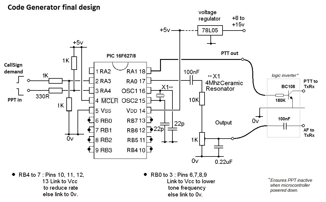
The circuit
This small project was developed after a discussion regarding the use of call-sign idents being used for DF events. However, the unit can be used for any application that requires any form of morse idents to be generated, such as repeaters. This current version has been modified intended for use at the start & end of a transmission, useful for 2m & 70cm group working.
The design is based on the Microchip’s PIC16F628A. This is one of the smallest in the range but is electrically programmable and is quite adequate for the task. It has a total of twelve input/output ports. Ten ports are configured as inputs. Port (RA4) accepts the PPT input from a microphone and generates specific (pre-programmed) code when transmission begins (Hi-Lo transition) and a second (pre-programmed) code when the PTT is released (Lo-Hi transition).
A second input, (RA3) is activated by a Lo to Hi transition from a dedicated push switch. This generates a specific (pre-programmed) code (eg callsign). A further four input ports (RB0 to RB3) are used to vary the tone pitch, these are binary count values, a low on all pins produces the highest tone (apprx. 3kHz). Similarly, ports RB4 to RB7 are used to set the code character rate. Again these are binary count values, low on all pins produces the highest rate (apprx.15wpm)
The audio code tones are taken from port RA0, the level can be adjusted from approximately 0 to 500mV, some filtering is provided to remove fast transitions from generating unwanted harmonics in the audio circuits.
A second output (RA1) provides the PTT output signal to the transmitter. This is mimics the input PTT demand, but is delayed on PTT release to allow time for the end –of-transmission ident to be sent. A small ‘daughter board’ was added to invert the PTT output signal. This ensured that the PTT output demand was ‘Hi’ (ie high impedance) when the unit was powered down (ie TxRx to receive).
The microcontroller is clocked at 4Mhz from a ceramic resonator, so the unit has an effective clock cycle of 1uS.
Components List
qty |
item |
1 |
330R ¼ Watt |
3 |
1K ¼ Watt |
1 |
10K ¼ Watt |
1 |
180K ¼ Watt |
1 |
1K sub.min vertical preset |
2 |
22pF ceramic |
2 |
100nF min. ceramic |
1 |
0.22uF min. ceramic |
1 |
4Mhz ceramic resonator |
1 |
78L05 voltage regulator |
1 |
16F627/8 PIC |
1 |
BC108 (plastic) |
.JPG)
The completed unit
Creating a code ident/phrase
The program looks rather complicated, however it has been written so that users can create their own morse message with no little programming ability. All that is required is to enter the morse message as ‘dit’ and ‘dah’ together with character/word spacings in the table area provided.
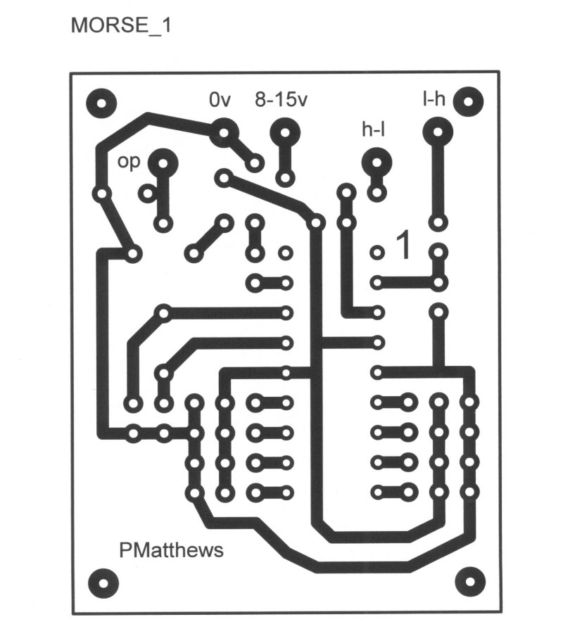
Simple PCB for ident unit
.JPG)
Ident unit connects into microphone lead
The program code *
The program consists of a main body that calls four main subroutines, ‘init’, ‘Get_Offsets’, ‘Chk_HILO’,’ Chk_LOHI’. These make further calls to subroutines: ‘Call_sgn’, ‘Rd_tbl’, ‘gen_tone’ and ‘gen_dly’. The code table entry points are labelled: ‘startTbl’, ‘csnTbl’ and ‘endTbl’.
The main body code first executes the ‘init’ subroutine. This setup the two ports, PORTA bit 0 & 1 are the only outputs, all remaining PORTA bits and all of PORTB bits are configured as inputs.
Next the ‘Offsets’ are executed. Here, PortB bits 4 to 7 are used to adjust the delay period, any binary number (ie 4bit) will increase the delay periods and slow the rate of the morse code (connect pins to 5v to delay time in steps of 25mS).
PortB bits0 to 3 are used to adjust the tone frequency, any binary number (ie 4bit) will increase the tone period and so lower the tone frequency.
The main body of the program continues with calls to subroutine (‘Chk_HILO’). The code ‘waits’ for a Hi to Lo transition on PortA. Once a transition is detected, the data table pointer is set to the appropriate code table (ie ‘startTbl’) followed by execution of the code to generate the tones (‘Rd-tbl’). Execution then returns to the main body of the program and a call is made to a subroutine (‘Chk_LOHI’) which waits until the EITHER the PTT is released OR the push-button on RA4 is pressed (Lo to Hi). If the PTT has been released the end code table (‘endTbl’) is executed else the callsign code is executed (‘csnTbl’).
During the reading of the selected code table (‘Rd_tbl’), the generation of the audio tones (gen_dly) uses three ‘nested’ loops to provide the pre-selected (hard wired) tone frequency . The inner-most loop (Tn1) sets up the 1/2period time for the tone and a toggle action of PortA bit0 is achieved by the Exclusive-OR instruction (XORWF). The tone period can be adjusted by any input value on PortB bit 0-3.
The period of a dit or dah tone is set by the duration of the outer loop parameter (t2) but is increased by any input value on PortB bits 4-7.
The delay time between morse element (dit or dah) is referred to as the interchr delay and is equivalent to the length of a dit.
The subroutine ‘var_delay’ is used to generate the appropriate delays at the end of a letter or word. This time delay is also adjusted by the offset that results from a binary input on PortB bits 4-7.
The end of a data table ‘is detected’ by the presence of the: end of a character (chr), the end of a word (wrd) or the end of the table (tablend). Appropriate delays are used to effect the end of letter and end of word. Whereas, an end of table character, will result in a repeat of the whole sequence, including a wait for a input transition. The program will simply continue to generate the code if either of the trigger inputs remain at their appropriate logic level.
*Source code free on request
-----------------